Jepp Valve Specification
Pressure
| Maximum allowable (PN) | 10 bar |
|---|---|
| Adjustment range (Ps) | 1–3 bar |
| Preset at | 1.4 bar |
Temperatures
| Operating temperature — fluid inlet | 0°C (frost excluded) to 65°C |
|---|---|
| Operating temperature — fluid outlet | 0°C (frost excluded) to 110°C |
Compatible fluids
- Water
- Glycol solutions (maximum 50%)
Threads
Compression fitting for 15 mm copper tube.
EN 1254-2 with 1/2″ male on body, reference ISO 228-1.
Materials used
| Brass parts in contact with water | DZR brass (CW602N) |
|---|---|
| Brass parts not in contact with water | Brass (CW617N) |
| Plastic parts in contact with water | PA and POM |
| Gaskets | EPDM |
| Spring | Stainless steel (304) |
WRAS Certificate
WRAS Product Approval Certificate 251215711
Pre Installation
- Ensure pipework is flushed through before installing the JEPP valve.
- Position the JEPP valve so that the water supply flows in the direction indicated by the arrow on the JEPP valve.
- If necessary, fit a filter on the mains water supply to eliminate any impurities which might impact normal operation and damage the JEPP valve.
Installation
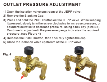
- Close the isolation valve located upstream of the JEPP valve.
- Drain the heating system.
- Insert elbow ① into the JEPP valve body. The length of elbow ① can be adjusted according to the pipeline distance, with an adjustment range of 0–10 mm. (See Figure 1.)
- Once aligned, elbow ① can then be tightened to the JEPP valve body.
- Connect the Discharge and Vent Elbow ② to the Discharge and Vent Port ③ on the JEPP Valve, ensuring the orientation is aligned with the Discharge and Vent Pipe. The Discharge and Vent Pipe must be connected to a drainage system, or to a location where overflow will not cause damage.
- After installation is completed, open the isolation valve located upstream of the JEPP valve.
WARNING: DO NOT cap Discharge and Vent Port ③ on the JEPP Valve.
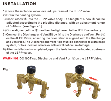
Suggestion: For heating engineer use only. If filling takes a long time, then use the retaining clip. First, press and hold the PUSH button to insert the clip; then, to remove it, press the button and pull the clip out. (See Figure 3.)
Important notice: It is imperative that the clip is removed, and that the PUSH button is released after filling the system.
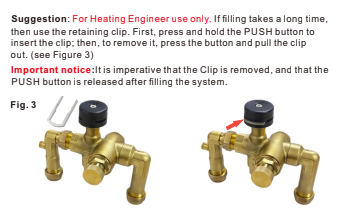
Outlet Pressure Adjustment
- Open the isolation valve upstream of the JEPP valve.
- Remove the Blanking Cap.
- Press and hold the PUSH button on the JEPP valve. While keeping it pressed, slowly turn the screw clockwise to increase pressure, or counterclockwise to decrease pressure, using a hex key (size S5). Continue to adjust until the pressure gauge indicates the required pressure. (See Figure 4.)
- Release the PUSH button, then securely tighten the cap.
- Close the isolation valve upstream of the JEPP valve.